Installation of a Factory Fuel Subtank
**** NEW INFORMATION 3/29/03****
There are a number of folk who have recently acquired subtanks from SOR. Unlike the one I bought a few years back, SOR is now importing and selling subtanks from the 105 series, and marketing them as 80 series tanks. There may be some advantages in using the 105 series subtank, but unfortunately there are some issues with this as well. Here is a summary of the details that I am aware of at present:
As of this writing I don't know of anyone that has successfully installed one of the SOR 105 series subtanks into an 80 series.
Installing the 80 Factory subtank into an 80 series.
The Toyota Factory subtank has a 50 litre capacity (13.2 US gallons - mine seems to take 14 US gallons on a fill from empty). Not a huge capacity - but a welcome addition to the smallish main tank.
In search of some additional fuel capacity I looked into the large Oz aftermarket tanks, but all appear to 'hang' down too low for my comfort. Given the 80's articulation prowess, I just felt that anything that hangs down below the chassis rails at the rear would be just waiting to be smacked by a nasty rock at some stage.
Given that, the factory subtank sits nice and high (it in fact sits above the spare tyre support crossmember) and is very unlikely to ever be compromised.
Before we start the installation, the following should be noted:
As far as I know the US 80 doesn't have the necessary ECU to control the subtank's fuel pump. In the Oz spec 80 the fuel pump will automatically shut off if either the sub tank runs dry or the main tank is full. I had to provide my own scheme to transfer the fuel - see below.
The 4 captive nuts in the body do not exist on the US 80. I had to drill two holes into the rearmost ribs and install captive nuts. The front most ribs had the holes but no captive nuts - I had to install those too.
This picture shows the USDS of the rear rivnut after installation, the USPS is similar. The hole on each rib must be drilled for the rivnut. A Unibit step drill makes a neat job of this. Installation is easy due to the reasonable access available for the tool.
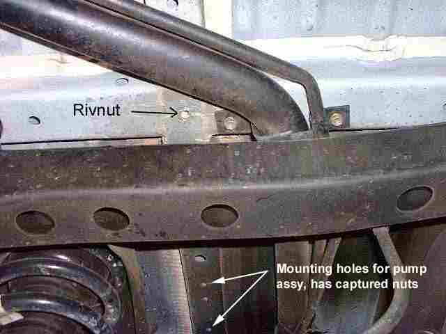
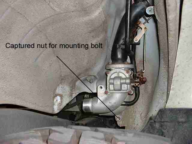
The following shows the USDS rivnut after installation. The hole for this rivnut was already present in the body - fortunate since drilling it would have been quite a challenge - it sits above the chassis crossmember. You can also see the two captured nuts in the body rib that are used to support the fuel pump and solenoid bracket assembly.
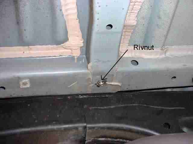
The following shows the USPS rivnut after installation. Again the hole was already present, but installation of the rivnut was a bit of a challenge due to the restricted clearance between the body rib and the chassis crossmember. Careful selection of the bolt length to use with the tool is essential to ensure not getting yourself locked in - i.e. rivnut installed and bolt impossible to remove ;-) Even then I ended up using a crowbar to push the body away from the chassis just enough to get the bolt I used out...
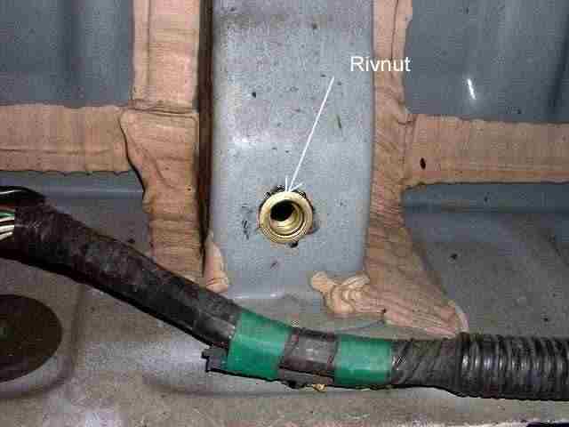
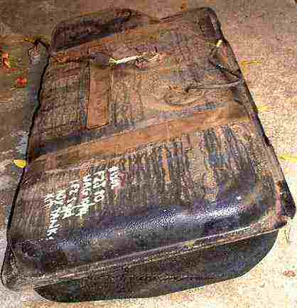
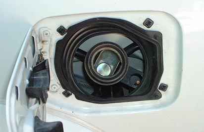
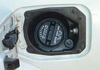
The following picture shows the dual filler. Push the knob in (the normal position to close the fuel lid) selects the main tank, pulling the knob out selects the sub tank. The hose diameter for the fuel outlets is 1 5/8" (ID) and the breather inlets is 1/2" (ID). I could only find 1 3/4" (ID) gasoline rated hose locally. I double clamped each end of the hose to ensure the hose was well sealed to the hardlines. The tank came with all the hardware to fit it - including a replacement filler shroud with the hole to allow the knob and rod to fit through.
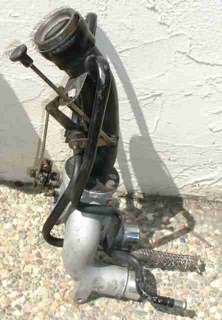
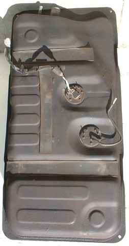
The next picture shows the subtank prior to installation. Needs a bit of a clean too (picture on the right is after cleaning & repainting). From the picture you can see the fuel outlet (that goes to the transfer pump) in the middle right. The harness and connector that is visible on top of the tank provides the signals from the sender and the fuel tank empty sensor. I also popped both the sender & pickup units out of the tank to verify they were functional. The inside of the tank was spotless - just like new! The fuel pickup pipe has a nice screen filter on it - though the outlet end was jammed with what looked like flower debris - some compressed air soon cleaned that out! I'm quite impressed with the factory tank - there are internal braces to reinforce the tank and baffles to prevent too much fuel sloshing. There is also a fuel trapping contraption around the pickup pipe to assist in getting all the fuel out of the tank even when bouncing around offroad.
Wiring colours (on subtank
connector):
Brown
Ground
Red/Yellow Empty Signal (Switches to Ground
when empty)
Yellow/Blue Sender Signal (Variable resistor,
relative to Ground)
Another colour combination that has been seen (on subtank connector):
White/Black
Ground
Yellow/Green Empty Signal
(Swiches to Ground when empty)
Red/Yellow Sender Signal (Variable
resistor, relative to Ground)
The electrical control of the transfer pump and solenoid required me to design a replacement for the ECU control system that the factory Australian 80's came with. Firstly, the transfer pump switch is a momentary contact switch, i.e. when you push it, it closes the contacts and when you release it switches back off. I built up a circuit to convert this momentary action into a toggle action. The circuit also has an input from the subtank empty switch (part of the subtank sender) so that it will deactivate the relay (that provides +12V to the pump, solenoid and transfer switch light) when the tank is empty. Unlike the ECU system, if the main tank fills completely and the subtank is still not empty, only the operator can stop the fuel transfer. This is ok in practice as the fuel will just go up the main tank's breather and flow into the breather of the subtank - i.e. re-circulate the fuel.
You can find the schematic for this circuit here: PDF schematic. On the left of the picture is the factory fuel transfer switch. On the right is the finished board - built on a piece of protoboard and then potted with epoxy resin. 2025: I continue to make transfer modules (see the pictures after this one) $30 each (including mail within the US). If you want to buy one send me an email.
Original prototype:
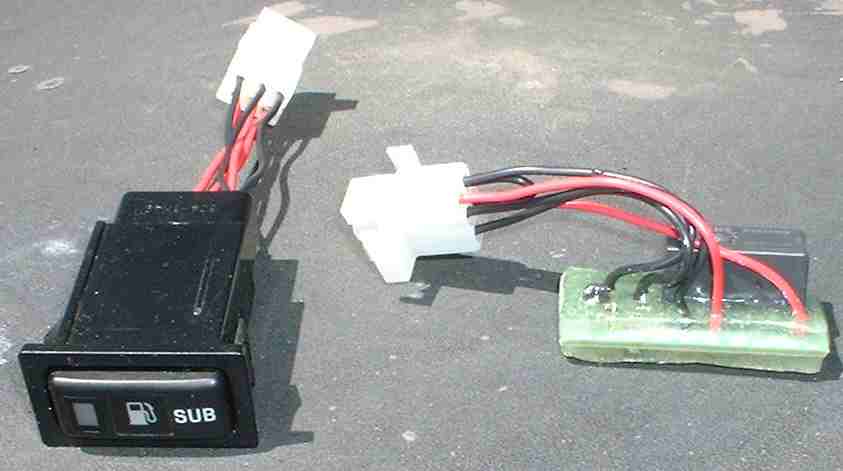
Here's a picture of the first transfer circuit modules that I WAS selling if you don't want to build your own. The connections match the connections in the PDF schematic.

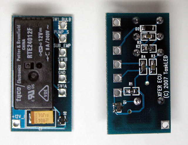
Here's a
picture of what I am NOW
selling (Oct 2007). This is
the same design as above, but it is now on a production PCB.
Functionally they are identical, the new ones just look pretty and have
silkscreen labeling of all the connection points. The latest ones (as
of 2021) are white with black lettering. No change in function.
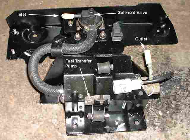
The following picture shows the refurbished (sandblasted & painted brackets) fuel transfer assembly. It bolts on upside down to the underbody just behind the main fuel tank. The inlet & outlets require 5/16" ID hose. The solenoid valve acts as an anti-syphoning device. I removed part of the bracket assembly (the top right of the picture) to make it easier to fit into my 80. I think on the factory original installation the outlet connects into the main fuel tank through the top of the tank. On my implementation I tee-ed into the main tank's breather line - so I didn't need the extra bracket length & hardline - it also would have run very close to the exhaust pipe - so a quick trim with the tin snips was called for.
Finally after many months, everything was ready for the installation. Due to the nature of the installation, you really need to finish it off in one day, otherwise you'll be driving around with vent or filler pipes open... I started around 1:30pm, and also helped swap a set of 863 springs into Amando's 80, and finished around 6pm. Another 2 hours later in the evening to strap in the subtank and hook up the hoses to it.
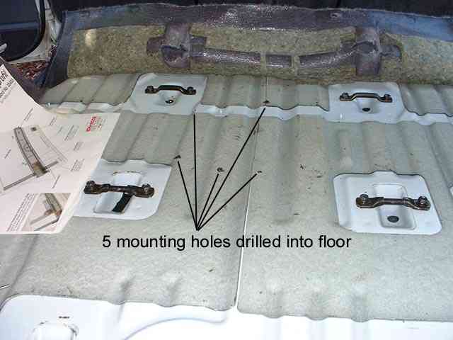
The job started with pulling off the carpet and getting access to the cargo floor area. The following picture shows the 5 holes that I had to drill into the floor to allow the fuel transfer assembly brackets to be bolted in place below. This is the only part of the installation that required a helper - to tighten the bolts from above while I held the assembly in place from below.
The following pictures shows various stages of installing the dual filler in the vehicle. The first picture shows the view from inside the jack cubby hole once the filler shroud and dust shroud have been removed. The right picture shows the new dual filler with the dust shroud installed.
This picture shows the view of the dual filler installed. The plastic stone/debris shield has been removed for easy access. The US 80 has the necessary captured nut for the lower fuel filler mounting tab. There is a 2nd mounting tab on the dual filler, but no obvious place for it to bolt to. I found that once the shroud was installed and the bottom mounting tab and all 4 hoses secured - the filler was not 'going anywhere'!
The next picture shows the view from the other side with all the hoses installed. Note the double clamping.
The fully installed dual filler and shrouds. The pull knob to the bottom right of the filler cap selects the main tank (when pushed in) or the subtank when pulled out. The result is a fully factory original look.
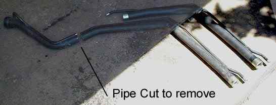
The following picture shows the original filler pipe (bottom) and the replacement filler pipe. To remove the original filler pipe it was necessary to cut the pipe on the vehicle. Maybe it's possible to remove it without cutting - but I wasn't able to find a way to 'work' it out - so the hacksaw came to the rescue - fortunately it's thin wall pipe and didn't take long to cut!
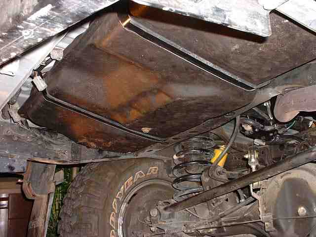
Believe it or not - the following picture shows the view from the rear (looking up) of the installed sub tank. Now that's what I call neatly tucked up!
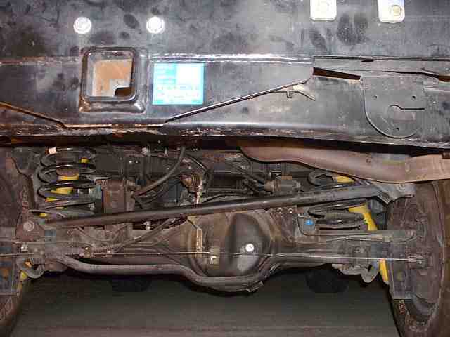
See, the subtank really is installed (finally!). You can see that it actually sits above the bottom of the chassis rails - and on the middle left you can see the bracket that supports the crossmember that the spare tyre hangs from. I'm very pleased with the final result. Near the top left you can see two connectors (male/female) that haven't been plugged together yet. The US 80 has the connector and harness wiring to plug into the subtank's sender and empty sensor - unfortunately I don't think the US ECU knows anything about the subtank etc. In the picture you can also see the two straps to hold the fuel tank up. Each strap has a bolt hole in each end - the bolts go into the captured rivnuts that I had to insert into the body - see top of this page.
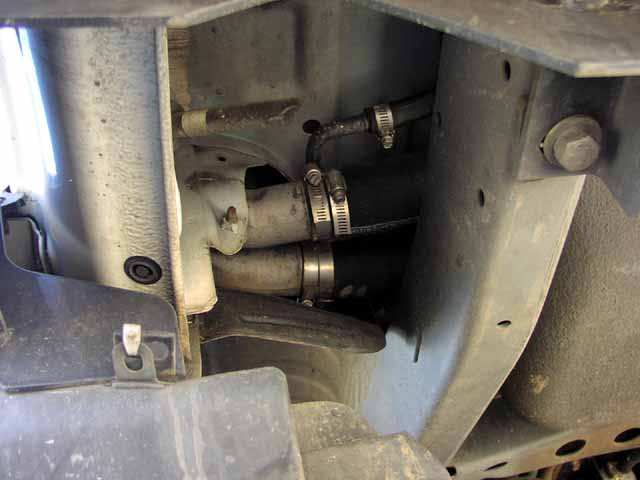
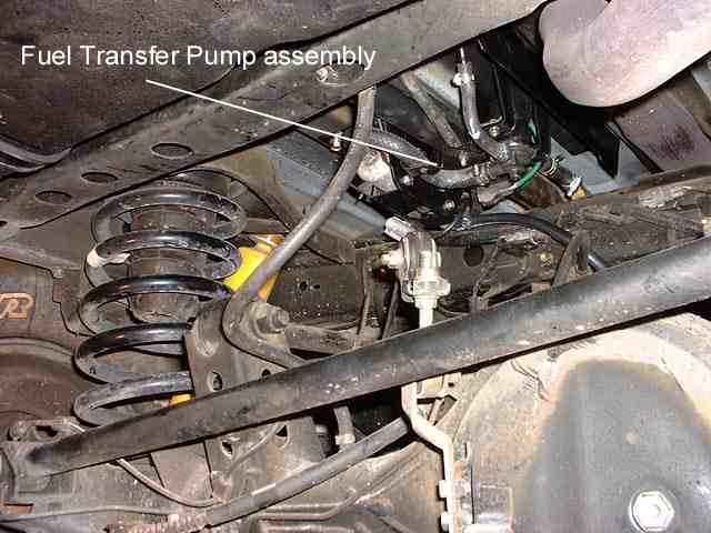
This picture shows the fuel transfer pump assembly bolted in place and all the hoses hooked up. It also is nicely tucked up - just behind the crossmember behind the main tank. The outlet of the transfer pump assembly is tee-ed into the fuel breather line from the main tank. The breather hose is 1/2" ID, while the outlet hose is 5/16". I used a brass 1/4" NPT fitting with two 1/2" barbs and one 5/16" barb screwed into it.
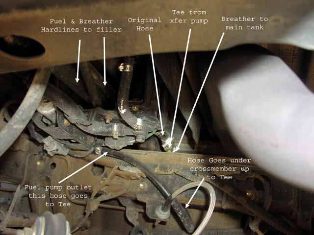
The next shot shows all the hoses going to/from the transfer pump assembly. Yeah, this is a recent picture - brake lines are new extended stainless braided units.
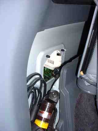
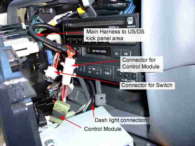
Time to install the wiring! This picture shows the main panel pried back sufficiently to gain access for installing the new harness, control module and connectors. The control module described previously, converts the momentary action subtank switch to a toggle action and also automatically turns off when the subtank is empty. The subtank switch has a backlight so I connected it into the main dash lighting by splicing into the wiring of the backlight ring around the cigarette lighter. The main harness is fished through to the US/DS kick panel area - which is where I brought in the wiring from the subtank and fuel transfer pump and also has the main connection to earth and IGN +12V. I obtained IGN +12V by splicing into the 30A fuse protected DIFFLOCK power - a BLUE/BLACK wire.
Note: The dash dimmer system on the 80 is based on +12V connected to one side of each bulb and the dimmed (0V to +12V) signal to the other side. With 0V on the dimmed signal the bulbs will have 12V applied across them - maximum brightness. So, you have to tap into both the +12V and dimmed signals.
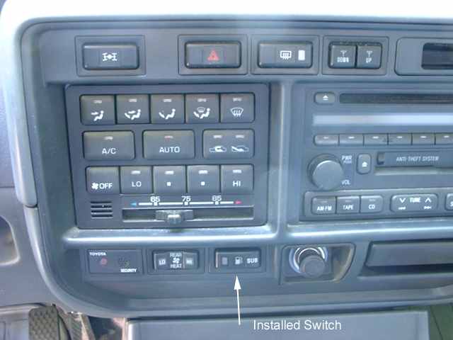
This shows the installed subtank switch. No more free switch blanks left here now.
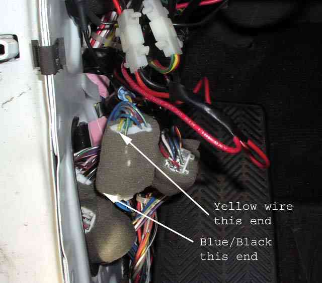
This is some of the 'stuff' that hides behind the kick panel. Considering it is a main factory wiring junction, I figured it was a good a place as any to add my kludge in as well. The +12V connection is spliced into the DIFFLOCK BLUE/BLACK wiring to obtain IGN +12V. In the picture the connector and splice have been pushed back in and can't be seen. The Ground connection is to an existing ground connecting bolt - if it's good enough for Toyota, then it's good enough for me.

This picture shows the connector that the power is spliced into. One end of the connector has the thick BLUE/BLACK wire while on the other end of the connector it is a thin yellow wire. I chose to splice onto the yellow wire since it was easier to crimp into.
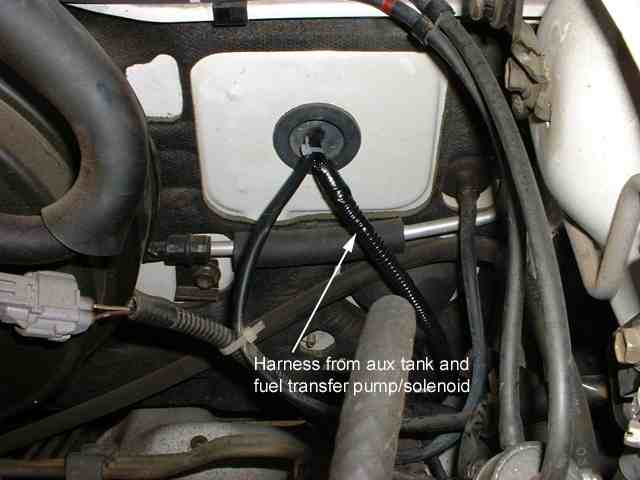
This is in the engine bay, on the US/DS firewall. I used an existing grommet entry point to feed in my harness. In the harness is the controlled +12V to the pump/solenoid assembly and also the Ground, Sender and Empty wires from the subtank.
The subtank wiring connection at the rear of the vehicle. The US 80s have the connector to the subtank in the rear harness - I didn't know where it went and couldn't be bothered figuring it out so I just cut it off- leaving long enough pigtails to splice it into my own wiring harness. This connector mates perfectly with the connector on the subtank - for a neat install. I then ran my new harness along the US/DS chassis rail where it met with the pump/solenoid harness.
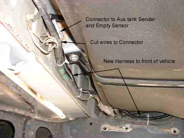
This shows where the pump/solenoid harness gets merged into the subtank harness. The resulting harness then leads up to the firewall - shown previously. I connected the ground for the pump/solenoid to a stud on the body - an existing factory running board stud.

There is a gauge pod that comes standard in other countries (like Australia) that mounts where the sunroof controls go. The gauge pod contains a fuel gauge for the subtank.
Wiring for the gauge pod:
Yellow/Red
To subtank sender (variable resistor - relative to
ground) .
Blue/Red Gauge +12V power
(connect to fused +12V ignition switched).
Black
12V lighting supply (connect to fused +12V ignition
switched) .
Blue
Rheostat dimmer connection (variable
resistor - relative to ground).
Grey
Gauge ground
![]()