Skid Plate & Compressor Relocation
With the s/charger installed - a new home for the Thomas compressor was needed.
The engine bay had no viable spaces left for the big compressor.
It was time to look elsewhere in/under the vehicle.
I've always looked at the toyota transfer case skid plate and been less than impressed by it's sturdy construction...
In thinking of a replacement I figured that a full width skid plate would provide a perfect location to mount the air compressor. There is a relatively large cavity just to the left of the transfer case - just large enough to hold the compressor in a suitable water proof box.
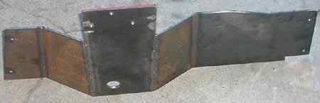
The work then started, with cardboard in hand I cut up a set of templates to determine how it would fit together. The first step was to fabricate the USDS sections first. The following picture shows the pieces bolted on and tack welded together. I also drilled a hole in the transfer case section to allow access to the drain plug. The section under the transfer case is 1/4" plate, the other pieces are all 3/16" since they really are intended only to support the air compressor - since they are actually tucked up higher than the central cross-member.
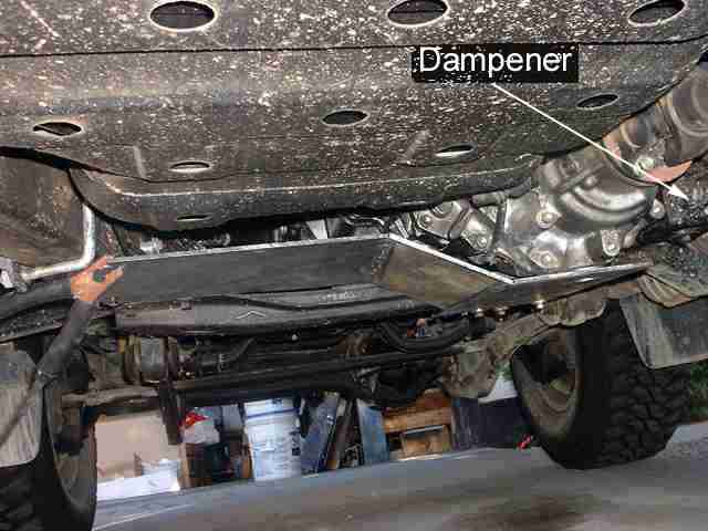
Just to the right of the transfer case you can just see the dampener block that is bolted to the side of the transfer case. It is a big rubber doodad that is presumably intended to dampen vibrations from the transfer case. Anyhow, it is in the way of the right hand section of the skid plate (that is not tack welded in place yet). I ended up removing it and welding a couple of new tabs to it and mounting it upside down - this gives me much more room to fit the skid plate in place. Presumably it will still dampen any vibrations. Of course the most expedient thing would have been to just throw it away ;-)
The next picture shows the fully assembled (though only tack welded) skid plate. The 1/4" skid plate under the transfer case is angled down by inserting a 1/8" plate between the crossmember and the rear two mounting holes. This introduces a sufficient pitch to clear the rear bottom of the transfer case.
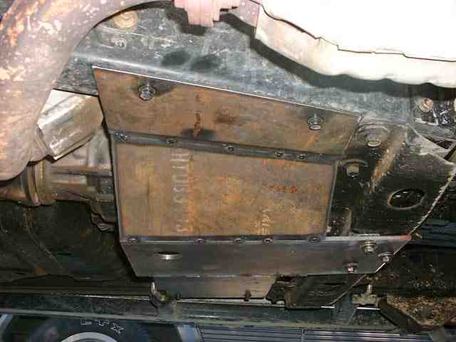
This picture shows the rear view of the tacked welded skid plate. The Thomas air compressor will end up sitting in a water proof box above the left skid plate member - i.e. just left of the transfer case.
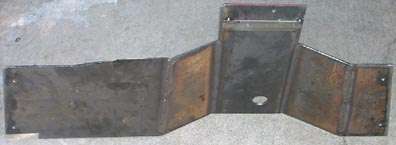
The next two pictures shows a top view and bottom view of the fully welded skid plate.
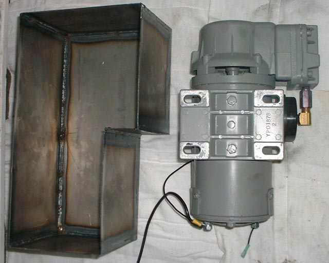
This picture shows the cover section of the box for the compressor. The narrow section of the box is just wide enough to clear the mounting plate on the bottom of the compressor. The wider section of the box is to allow the compressor's head and air inlet and outlet to clear. All seams of the box are fully welded to provide a weather tight enclosure for the compressor.
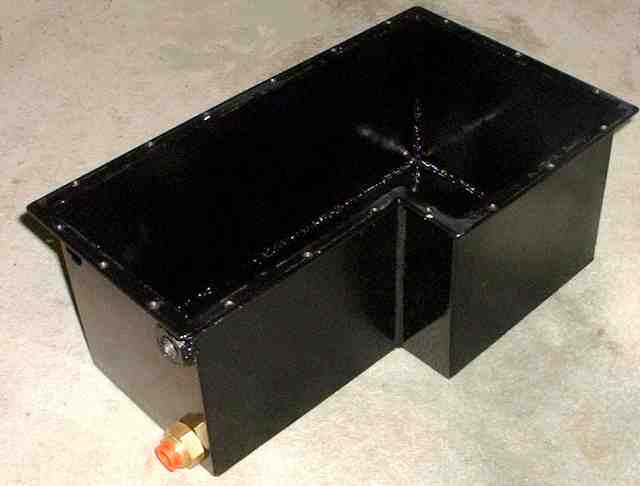
Next a flange (1/8" steel) is welded around the edge of the box. I drilled the flange and tapped the holes. These holes are used to fasten the lid (actually the bottom) to the box. From the picture you can also see three holes on the left end of the box. The bottom hole has a quick connect fitting already installed - this vents fresh air (from a hose that starts high in the engine bay) into the box - the compressor uses this fresh air for cooling and in turn 'sucks' it in an compresses it. The hole above the inlet hole has a 1/4" NPT fitting welded in place - this forms the bulkhead connection from the compressed air coming out of the compressor with a quick connect fitting. The compressed air is then run through a hose to the air tank mounted under/behind the winch on the ARB bar. The third hole, left of the outlet hole, will have another bulkhead fitting installed through which the power and ground wires will connect. The wires are run through another hose to the engine bay where they connect to a circuit breaker and the auxiliary battery.
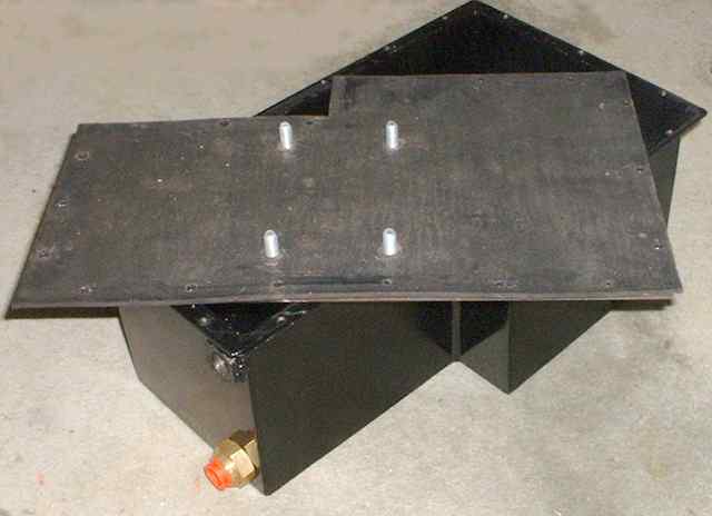
This picture shows the 'lid' with a 1/8" thick gasket. The four bolts are welded to the lid and are used to fasten the compressor. Holes are punched to match each of the bolt holes along the edge of the lid that fasten to the box. Once all bolted shut the gasket ensures the box forms a water proof enclosure for the compressor.
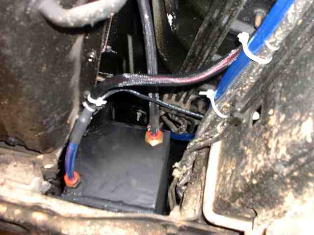
Finally, after months of waiting for nice sunny weather - and to build up enough motivation to get off my bum it was time to actually install the compressor and skid plate. The following picture shows the power and air inlets. Both use quick connect fittings through bulkhead connectors. The wires that go into the tubing are 'sealed' against moisture with silicone and then adhesive lined heat shrink was used. The air inlet leads into the engine bay and terminates inside the air filter housing. The other tubing that can be seen tie-wrapped to the chassis is the air outlet and runs to the front air tank that is mounted behind the winch.
The air inlet feeds air into the box (not just the compressor inlet) so that the compressor will continuously have a supply of cool air to compress. This should ensure that it doesn't overheat.
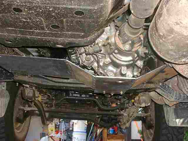
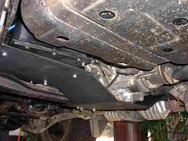
The view of the mounted skid plate with the compressor box bolted down to it.
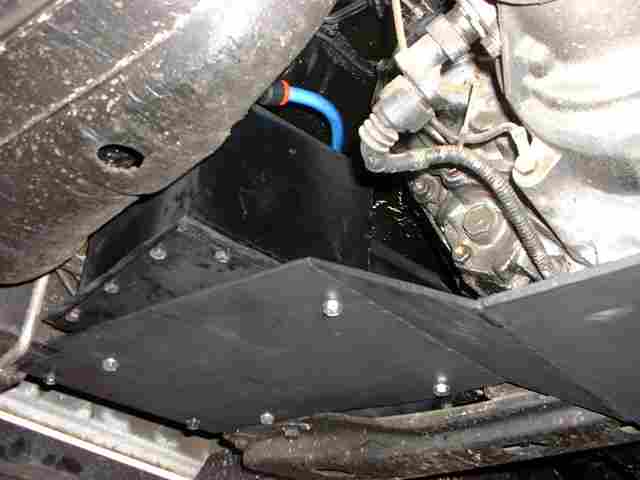
Another view of the compressor box. The strange angle that it is bolted down is necessary to ensure sufficient clearance to the transfer case & transmission - about 1 1/2" at the closest. The bottom of the skid plate (where the compressor is mounted) is just above the bottom lip of the fuel tank - i.e. it is pretty tucked up at that location.
![]()