More Suspension Lift
2023: Replaced the OME863 coils in
the rear for Dobinson dual rate (C97-145VT) coils. Impressively better
ride, bumps in the rear are much reduced, and generally a major
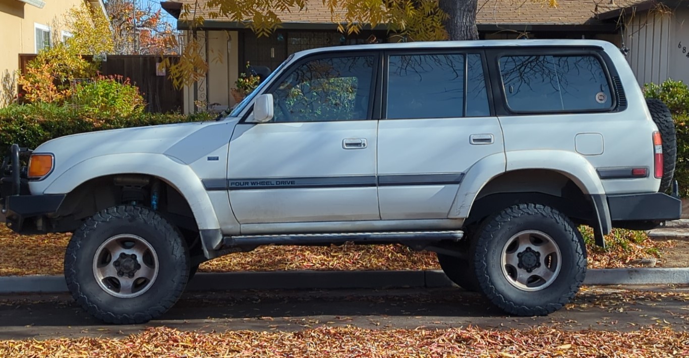
improvement. Picture below is how it looks with the current suspension.
Dobinson 3.5" dual rate front/rear (heavy), King shocks front, Radflo
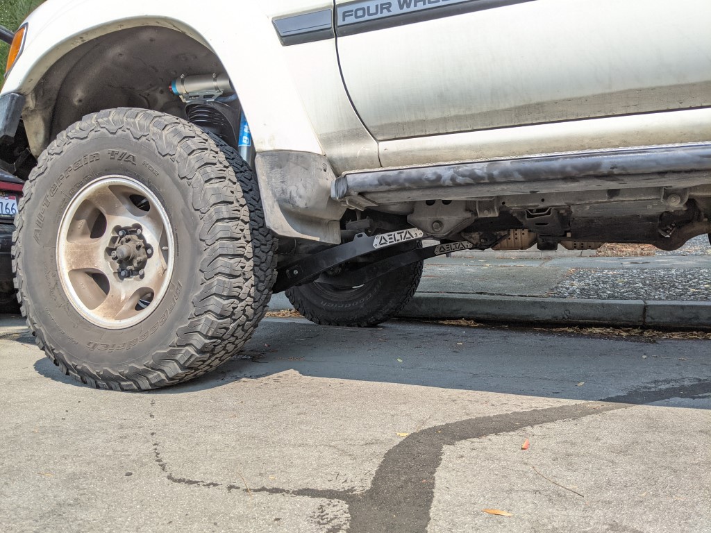
rear, Delta 3" arms and Delta rear panhard bracket.
2021: Upgraded to King Remotes in the front and Radflo 2" remotes in the rear. Much better ride than the OME shocks. 3 1/2" Dobinson dual rate coils (C97-144VT) on the front and OEM 863 in the rear. Replaced front sway bar drop brackets with 2" height to deal with the extra droop available with the King shocks combined with the very tall Dobinson coils.
Coils without any vehicle weight. Crazy tall!
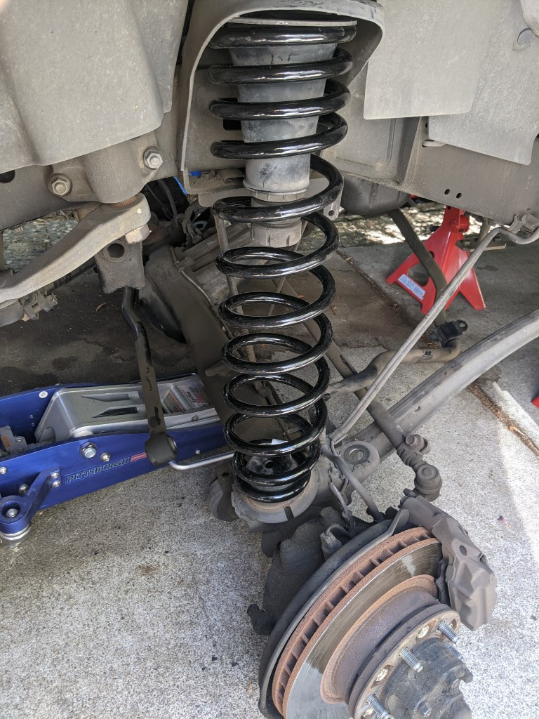

After removing the stock bump stops/dampeners the new King units have been installed and adjusted. All done :)

Old info, some dating from 2002:
I've been riding around on 850/863 OME coils for a few years now, time for some changes.
With the release of the OME 'L' shocks it was tempting to utilize their longer stroke.
Original suspension configuration:
The first step was to make up some new rear sway bar brackets to lower the sway bar mounting points. Even with the shorter OME shocks the rear sway bar links get pretty stretched when the rear articulates away from the chassis. I figured that lowering the rear mounts about 2" would be a good move. Toyota changed the rear sway bar brackets a few times during the 80's life, the '97 model's rear sway bar bracket is more complicated than some of the earlier models but with a cheap bender still easy enough to fabricate.
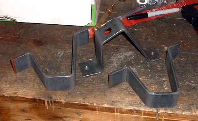
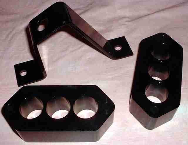
The following picture shows the prototype bracket in the center - with all the holes drilled. Beside it are more brackets that haven't yet been drilled. Since a group of us all wanted to make the same suspension modifications it was time to start a limited production run. After making the prototype bracket it now takes me about 10 minutes to bend up a bracket. The brackets are made from 3/16" x 1 1/2" steel (12" length).
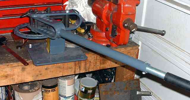
The following picture shows the cheapie ($50) bender that I used to make the brackets.
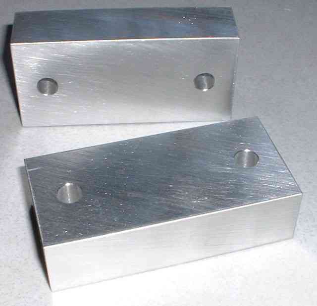
To utilize the OME longer shocks it is necessary to lower the front antisway bar a little so it doesn't hit the prop shaft on full droop. This is easily handled with some spacer blocks. The following picture shows two of the prototype blocks. My thanks go out to David for providing his mechanical design expertise and for getting the blocks & spacers fabricated.
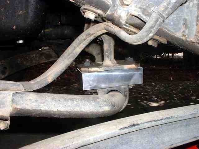
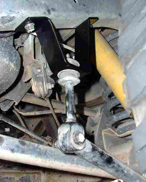
The next picture shows a prototype block installed to lower the rear of the antisway bar.
The next step to utilizing the longer OME shocks and to achieve a little more lift required spacers for the front coils. The following picture shows the two piece spacers prior to bolting them together. The spacers are machined to the same tear shape of the bump stop. The bump stop has two studs on the top that bolt it to the spring tower. These studs now bolt to the first spacer section. The second spacer section has threaded holes (where you can see some temporary studs in the following picture) that allow bolts to fix it to the coil tower.
![]()
The next picture shows the spacer sections bolted together and also bolted to the bump stop tower. The spacers have to be built as two pieces to facilitate assembly. The two spacer sections are bolted together with 4 recessed bolts that can be seen in the picture below and above.
![]()
Here are the rear sway brackets after powder coating and the rear bump stop drop blocks after anodizing.
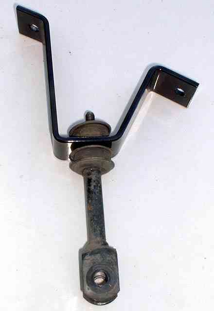
One of the rear sway brackets with the original rod installed ready for installing back onto the 80.
The rear brackets have been installed. The following picture shows the USDS bracket - need to get some dirt on there so it doesn't look so clean!
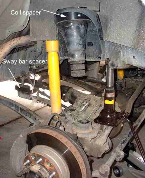
The next picture shows the spacer set installed - after anodizing. The spacers provide an additional 1 1/2" of lift over the OME heavy fronts. You can see the new SS brake line too.
![]()
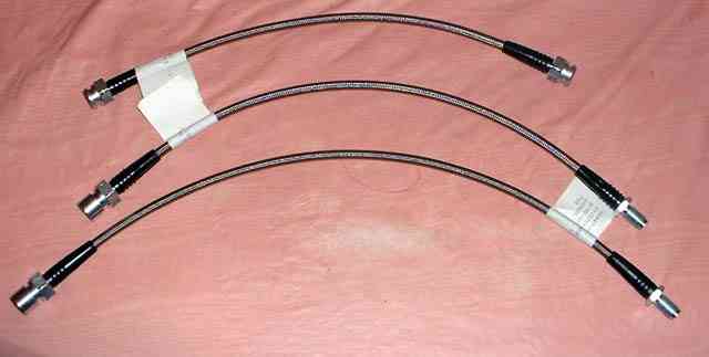
Here are the extended MAF Stainless Steel braided brake lines. The lines are at least 3" longer than the stock lines.
Part numbers are from top to bottom (on picture):
Right Hand front 90947-02817SS (short)
Rear 90947-02816SS (medium)
Left Hand front 90947-02815SS (long)
In preparation for the brake line install:
Make sure you have plenty of brake fluid available.
When you remove each of the stock brake lines, fluid will start to drip out - make sure you top up the master cylinder often to prevent it from running dry, otherwise you'll have a much bigger brake bleeding task later.
Have something to catch the dripping brake fluid.
When you install the lines DO NOT kink them.
During installation make sure the lines are routed so that DO NOT rub on anything. If they do, the SS braid will rub through whatever material is in the way.
The MAF lines pretty well fit perfectly. There are only three issues, and if prepared in advance are not a big deal. The first thing is that at each hard-line end, where the SS line has to be retained to the frame, you can reuse the stock hardware. The second thing is you really need to use a thin washer on the other side, see next picture.
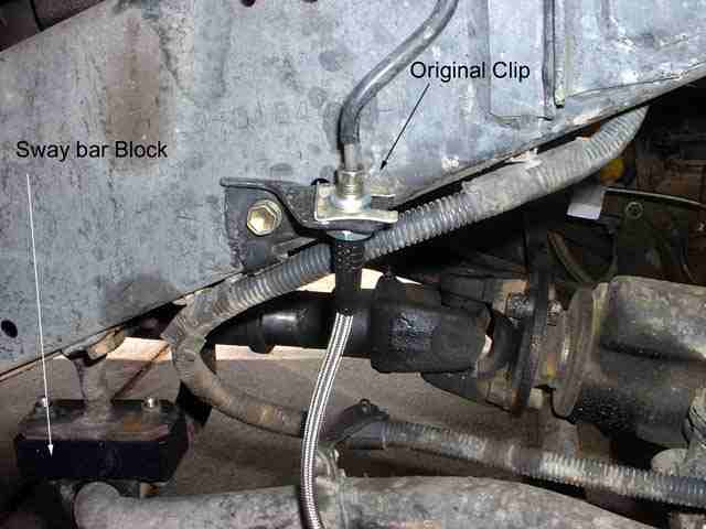
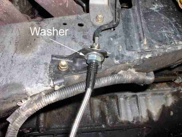
In this picture you can see the washer that was mentioned above. The hole in the OEM bracket is just a little big for the SS line and to make it a nicer install you need the washer. You need a total of 4 washers, one for the rear, once for the USDS front and two on the USPS front. The washer ID is 5/8" and the OD is 7/8". Make sure you get 'thin' washers.
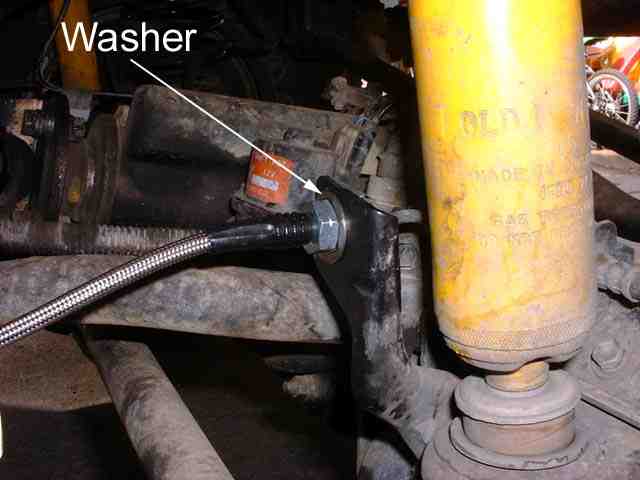
This is the bottom of the USPS brake line. This is where the third issue occurs. For whatever reason, the hard-line threaded part (the sliding collar) is somewhat flared and is tight to pull out from the OEM line and nearly impossible to get into the new SS line. The solution here was to gently file the hard-line end (not the threads, just the tip) with a spark plug file, you just need to 'ease' the flared edge a little so that it will clear the threads of the SS end. You DON'T file the hard-line itself, just the collar. Since it takes quite a while to get this fitting on, it pays to have a helper to plug the other end of the line or use a rubber glove & elastic band to 'stopper' the end. If you don't do this you will use quite a lot of brake fluid, since it just keeps dripping...
Once all the lines are installed, you just need to bleed the brake system - also a good time to flush the system. Start on the USPS rear, then USDS rear, the USPS front and finally USDS front.
Next in the suspension modification project was new rear lower control arms. Fabricated from 1/4" wall DOM tubing these arms are TOUGH. The ends are machined to take stock OEM bushings. Here's a picture of the prototype set - painted over a plated finish. The arms were made a little longer to compensate for a nominal 4" lift - to rotate the axle back to stock. This means we didn't have to make an adjustable upper control arm.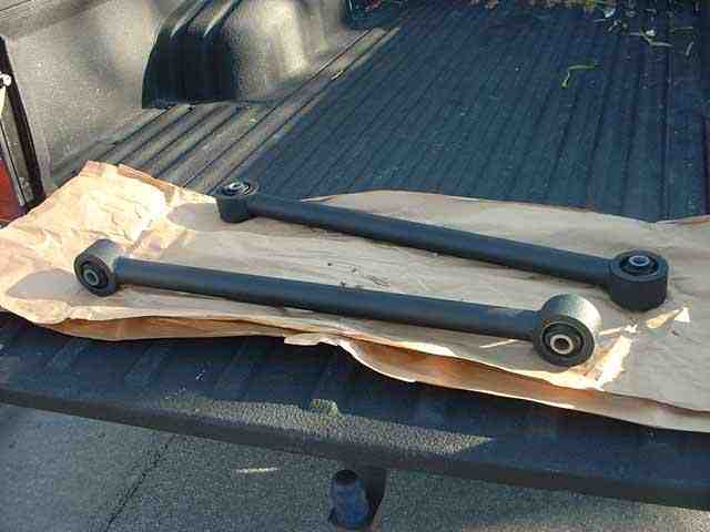
Installing the arms on David's 80. The entire rear end of the 80 is sitting on the jack stands. The two floor jacks are just to adjust the axle to allow the stock arm to be easily removed and the new arm to be installed.
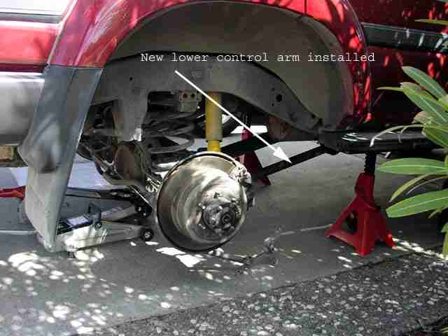
![]()