Auxiliary
Battery and winch for my 80 series TLC (This dates from 1999 era. In 2025 I have moved to a LiFePO4 battery and DC:DC charger)
Installing an Auxiliary battery in
an 80 series Land Cruiser is a relatively straight forward
procedure.
All mounting holes for a factory battery tray are already in
place on the US/PS fender.
One requirement is to relocate the factory washer bottle to make room for the factory battery tray.
Or if you have a supercharger, then you need a smaller bottle and you still need to relocate that. You can see a relocated generic washer bottle washer_scharger.
Following are the Toyota part numbers for the battery tray assembly and associated paraphernalia and quantities of each that are required.
In my case, deciding to save a few bucks, I only bought the tray from Toyota. I already had plenty of spare metric bolts from removing the stock bumpers and replacing with ARB/Kaymar. I bought a generic J bolt set from an auto store, which included rubber washers and nuts. I made the securing bar from some 1/2" right angle aluminium stock, you can see this handiwork in figure 1. The only other issue is that the tray does not come with the rubber gaskets that protect the cables that run through side holes in the tray. I couldn't be bothered trying to locate factory gaskets so I just used some 1/4" OD clear hose and slit it lengthwise. I then slid one slitted hose into each of the holes in the tray, you can just see that in figure 1.
Installing the battery tray is straightforward, figure 1 shows a picture of a typical installation.
In addition you need to get the cables, the battery and an isolation system of your choice.
Choosing Cables
Choice of battery cables depends upon your requirements, e.g. winch, auxiliary loads etc. At least 2 gauge wires should be used for all the main connections between the batteries, the isolator and vehicle ground. 1/0 gauge wiring is about as large as you would practically want to go.
If one of your requirements is to drive a winch, it is recommended that the relatively small ground cable on the original battery that connects to a lug on the engine be replaced with a heavier gauge.
Suitable raw cable and lugs can be bought from welding supply shops or Marine Supply shops (expect to pay more). The URL for one of the larger Marine Supply shops is http://www.westmarine.com.
The following table illustrates some typical cable specifications and the expected voltage drop due to cable resistance for various currents and lengths.
AWG |
Nominal OD |
ohms/1000' |
Voltage drop |
8 |
5/16" |
0.62 |
0.06V @ 100A for 1' of cable |
6 |
11/32" |
0.40 |
0.04V @ 100A for 1' of cable |
4 |
13/32" |
0.24 |
0.024V @ 100A for 1' of cable |
2 |
15/32" |
0.157 |
0.63V @ 400A for 10' of cable |
1 |
17/32" |
0.127 |
0.51V @ 400A for 10' of cable |
1/0 |
9/16" |
0.099 |
0.40V @ 400A for 10' of cable |
Choosing a Battery
Choice of an appropriate battery again depends upon your requirements, e.g. deep cycle, starting etc. In addition, some battery manufacturers recommend that both the main and auxiliary batteries be of the same type and age when charged in parallel via either an isolator or solenoid system.
Choosing an Isolation systemThis is the hardest choice to make and depends on whether you prefer an electronic system or a simpler solenoid based system. Note that the alternator in an 80 series is capable of outputting well over 100 amps into a discharged battery.
An electronic system is usually based upon 2 appropriately rated diodes imbedded in a large heat sink assembly capable of dissipating the waste heat from the diodes. This unit needs to be bolted to an area within the already hot engine bay. This system provides a simple isolation between the two batteries but does require removing the alternator output cable from the battery and connecting it to the isolator. One cable is then run from one of the isolator outputs to the main battery and a second cable from the remaining isolator output to the auxiliary battery. If you choose this scheme ensure that you have selected an isolator capable of at least 150 Amps
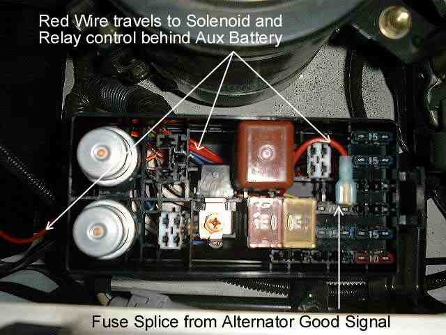
A solenoid based system is rather simpler and the 80 series provides a signal that is ideal to control it. One of the issues with a solenoid based system is how to activate the solenoid. There is a signal available in the engine bay fuse box (just behind the main battery) that indicates that the alternator is providing charge current (we'll call it Alternator Good). This signal is used to activate a warning light in the instrument panel if the alternator ever fails. This signal becomes active (+12V) several seconds after the engine is running and the alternator is producing charging current. A spade fuse splice/tap enables you to get easy access to this signal and to run a small gauge wire (14 gauge is perfectly adequate) to the solenoid coil. Click here to see a picture identifying the fuse connection.
The URL http://www.mechman.com have an ideal solenoid, Part Number 29-983 200Amp Isolation Solenoid.In addition to the Isolation system, if a winch is also in the plan, one recommended addition is a marine quality battery switch. Blue Sea Systems model 9001 (Blue Sea 9001) is a compact 4 position (one, two, both, none) 300A continuous (400A for 5 minutes) rated switch – available from http://www.westmarine.com. This allows the user to select either battery or both to run the winch, in addition winch power can be completely disabled – providing peace of mind in case some one decides to run your winch cable out and over to your hitch and activate your winch with a paper clip…
An added advantage of the ‘both’ position is a self jump start in case your primary battery fails. If you have chosen the solenoid based isolation system, then two relays (standard SPDT 30A automotive relays) are required to ensure that the solenoid is disabled when the engine is running AND you decide to provide winch power. These relays disable the charging solenoid while the marine switch is in any position other than OFF. Relay2 is an optimization to ensure that if the engine is not running (i.e. Alternator Good signal is off), that no power is provided to either relay regardless of the position of the marine switch - in this way, even if you forget to set the marine switch back to the OFF position, neither battery will be discharged. Of course in this case, when the engine is started again, the solenoid will also remained disabled preventing the auxiliary battery from charging. Click here for a GIF schematic of the complete solenoid based charging system.An example of a complete installation is shown in the following pictures.Figure 1. The first picture below shows the installed auxiliary battery and the relocated washer bottle in the top. All cables that rest on or near any sharp metal are covered with spiral cable insulation. This is an area you don't want a short to ever occur.
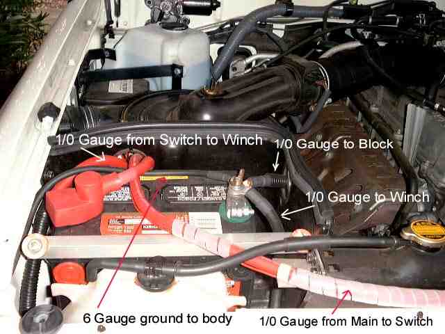
Figure 2. The next picture shows the main battery and the cable that leads off to lower left is the same cable as you can see in the above picture in the lower right. This cable runs to the marine switch to provide the choice of winch power. It also connects to the 200A solenoid to provide charging current to the auxiliary battery when the engine is running. Also visible on the negative terminal of the main battery is the 1/0 gauge replacement ground cable that runs to the original threaded hole in the engine block. A marine style battery lug clamp has been installed to allow the connection of the replacement 1/0 gauge ground cable and replacement 6 gauge ground connection to the body.
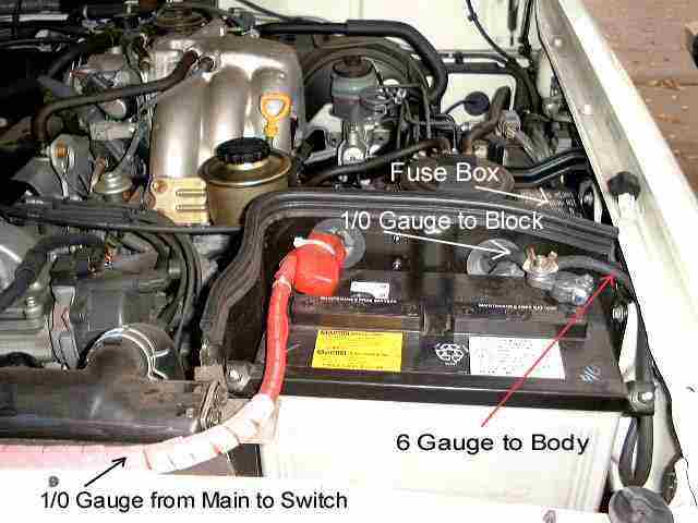
Figure 3 is a picture of the installed marine switch with the 200A solenoid and control relays mounted below it.
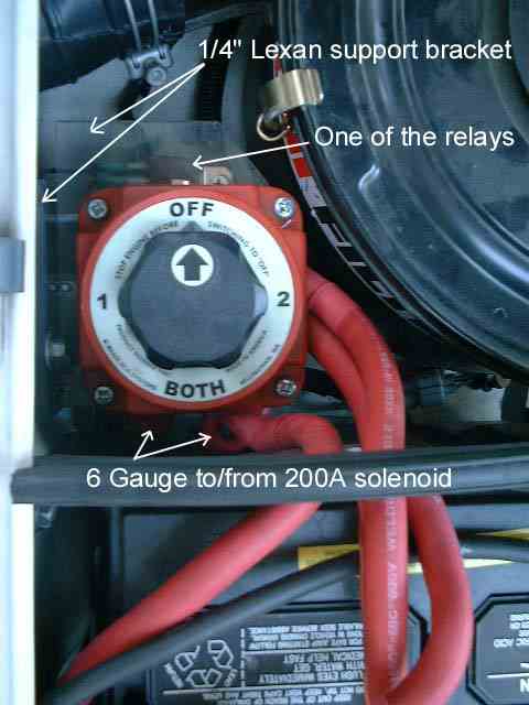
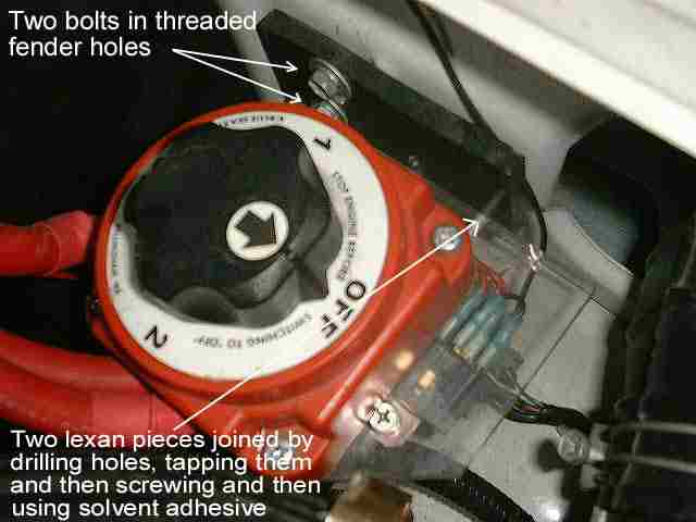
Figure 4 is a picture showing more detail of how the lexan support bracket is fastened to the fender.
![]()