
Mounting system for Thomas Air Compressor
To speed up the process of airing up tyres after a 4wd trip, it was time to get a decent air compressor.
The Thomas TA4101-DC air compressor was chosen, the next step was to mount it somewhere...
The pictures are of the prototype, unpainted at the time.
The following description also is pre-supercharger install. To install the supercharger I had to relocate the compressor to a new place. You can see what I had to build by following this link post-supercharger install.
After inspecting the already packed engine bay of the 4.5 litre 80 I decided the only viable place that was reasonably accessible, and sufficiently high was behind the air cleaner. It would be necessary to fabricate a sturdy and secure support for the 11kg (25lb) compressor. Initially I was thinking of mounting it using some brackets from the firewall and fender, but the thought of all that weight suspended on sheet metal did not 'sit' well with me.
After a couple of hours looking at various existing bolts in the chassis, the engine and the body a 'plan' started coming together. Another hour or so with scissors and cardboard in hand and I had some preliminary templates ready to transfer to the steel in preparation for plasma cutting.
The following picture shows the mounted compressor. The only modification necessary to fit it in required bending the bracket that the cruise control cable is clipped to. This is required to make room for the compressor's head to fit. The 40A circuit breaker provides power to the compressor via a standard 40A automotive relay that is controlled by a pressure switch. The outlet manifold consists of two T pieces that connect the compressor output (via a one way valve) to a pressure release valve (seen on top of the manifold) and to the pressure switch and to the high pressure hose that runs to a holding tank. The aux. fuse panel connects to the aux. battery. The two 10 guage wires bundled together run to the rear of the vehicle, one connects to a marine quality cig. lighter and the other is a spare that will 'come in handy' one day ;-)
If you want to check out the wiring for the compressor, click here for the PDF schematic file.
One of main considerations for the compressor support was that it had to be easy to bolt on and to then be able to bolt the compressor on it. I wanted something that could be removed in just a few minutes in case there was any need to access OEM parts, either by myself or by a mechanic.
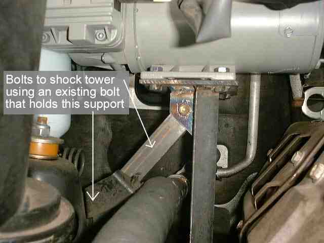
The finished support utilizes a vertical member that is securely fastened against a chassis rail (with a 3/8" u-bolt) and a bracket from an existing bolt on the US/PS shock tower. The bracket provides additional rigidity and stability to the vertical member.
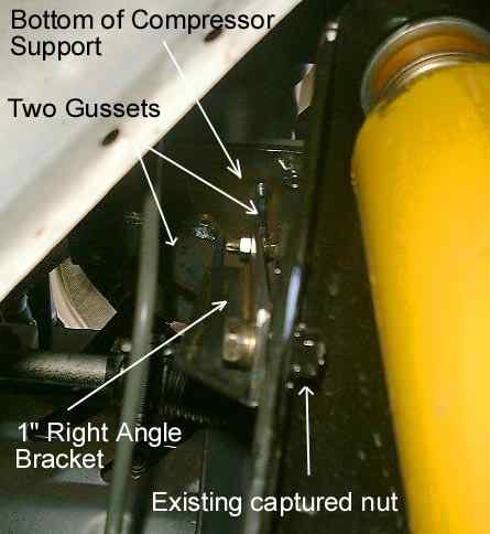
The following picture shows the detail of how the compressor is bolted to the support. The 4 nuts at the bottom of the horizontal support are tack welded in place - to ease the installation process. Also, the nut at the rear of the diagonal support bracket is also tack welded in place. The only change I plan is the addition of a heat shield (some 1/16" steel) sandwiched between the compressor and the horizontal support - to protect the compressor from the heat radiated from the exhaust manifold.
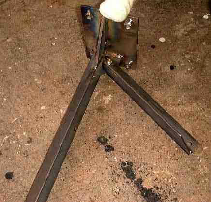
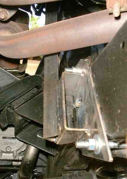
The following picture shows a back view of the compressor mounting support (with my nearly 10 month old son's sock covered foot posing for effect). The gussets and the horizontal support are all 3/16" steel, the vertical angle iron is 1 1/4" (1/8" thick) and the diagonal angle iron support is 1" (1/8" thick).
The following picture shows the diagonal support bolting to an existing captured nut on the US/PS shock tower. I just replaced the existing bolt (securing a bracket that supports an airconditioning line) with a longer bolt to also secure my diagonal support.
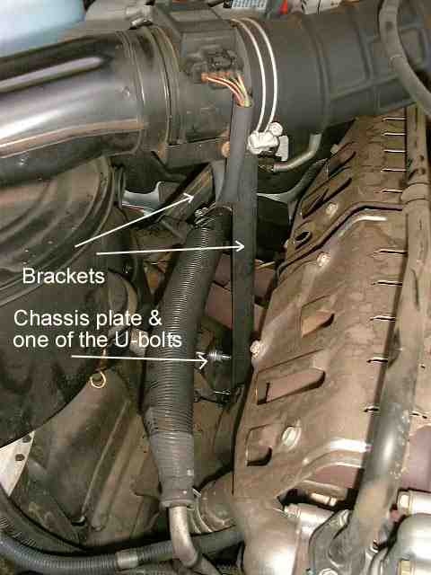
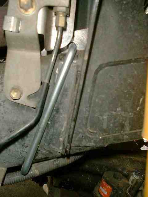
The following picture shows how the vertical support is u-bolted to the chassis member. The plate against the chassis has a 1 1/2 inch spacer welded to it, to which the vertical support is welded. This ensures that the vertical member clears the air conditioning line to the left of it (the one contained in the protective slit tubing).
The following shows a close up of the u-bolt that clamps around the chassis, just behind the shock tower. As can be seen from the picture there is only one spot that the u-bolt can fit - makes the choice easy ;-)
The following picture shows the vertical support bracket fastened to the chassis member. Note the welded head of a bolt in the middle of the flat plate against the chassis. The bolt is actually a 'pin' into an existing hole in the chassis to ensure the plate cannot slip around under the weight of the compressor when bouncing around offroad.
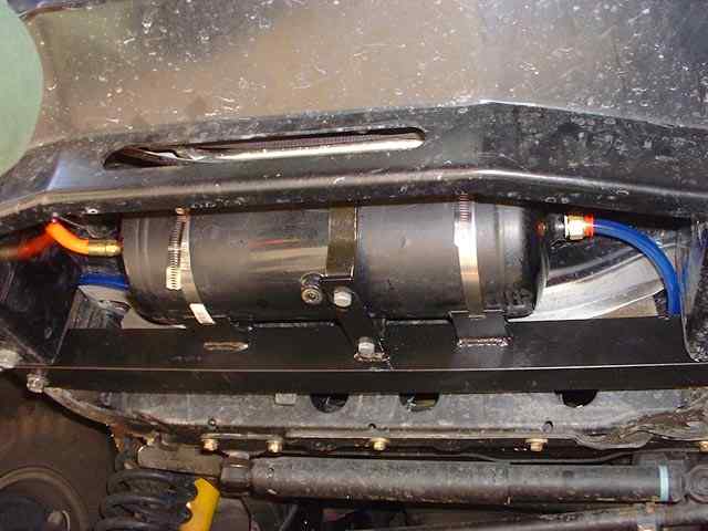
The next picture shows the 2 gallon (US) holding tank for the air compressor. The air tank is 6" in diameter and about 18" long, and is clamped with two large hose clamps to a bracket suspended between the two front chassis horns. I had previously made the right angle bracket (which is further braced on the inside) to protect the power steering "paper clip" line that is in front of the crossmember. To support the air tank I welded four tabs (two on each side) and then cut slots into each tab through which the hose clamp is 'threaded'. To further support the tank I welded on a tab to which one of the provided heavy duty clamps was bolted to. This clamp ensures the tank wont drop on the road in the event that both hose clamps give way ;-). The tank fits neatly behind the Warn 12000 winch. On the right side of the tank you can see a push fit fitting to which a polyurethane hose 'plugs' in that is routed to the bottom of the compressor manifold. The left side of the tank has a hose running to a standard quick release fitting to which an airline connects to fill tyres etc.
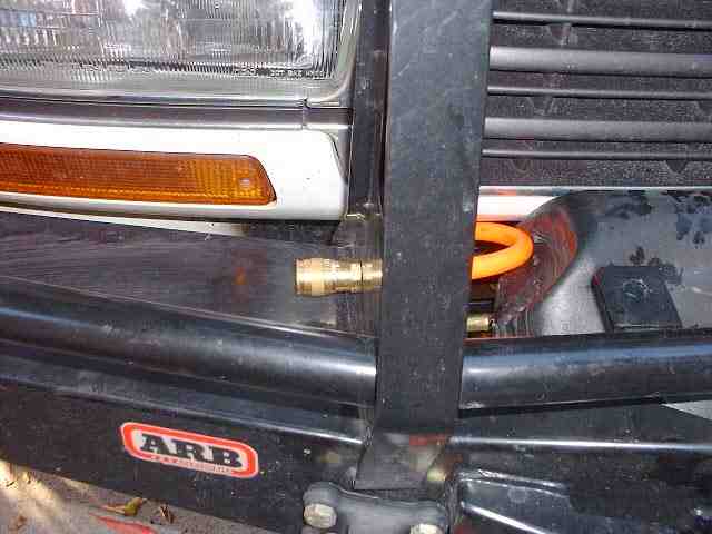
The following shows the quick release air fitting neatly fastened through the left ARB vertical member. I store a 25' coiled polyurethane hose with a tyre chuck on one end between the USDS headlight and the main battery - an otherwise unused storage spot. The hose is long enough to reach all the tyres on the cruiser, including the spare on the Kaymar.
The TA4101 is one of the largest 12V compressors that Thomas makes - one of the 'big guns'. The basic specs are:
In my case I was lucky that a friend picked up a couple of TA4101s for $300 a piece at a '4wd shop going out of business sale' and offered me first dibbs on the 2nd unit - he kept the first.
Some useful links to information regarding the Thomas compressor.
Other specialized bits that you will need (about US$30 + tax/shipping. http://www.mcmaster.com):
| Description | Function | MacMaster Part Number |
| one way valve | Prevents constant back pressure on compressor | 46105K39 |
| pressure relief | 125 psi safety valve - just in case... | 48435K724 |
| pressure switch * | Factory preset to cut off at 100psi, cut in at 80psi | 4154K611 |
* Big compressor style pressure switch - about $18.
If you desire a small compact pressure switch (105psi cut off, 84psi cut in) for about $21, visit the following URL http://www.airliftcompany.com/ and locate P/N 24544 in their 'easystreet' section. You can order via their toll free number (no on-line capability as of the time of writing). This is the most inexpensive compact pressure switch that I have been able to locate. This is the same company that I obtained my air tank from as well.
Regardless of the pressure switch you choose, you'll also need a 40A continuous rated relay to switch the compressor since the pressure switch is not capable of switching the compressor current directly.
In addition to the above, an assortment of air fittings, tee/cross fittings and airlines are required to complete the installation. The exact number and type is dependent on the specific requirements of your setup.
![]()