 Due to sufficient demand I have entered the physical
construction details of the outriggers into a CAD system and generated PDF's
that can be used as cutting and fabricating drawings. If you are interested in
these drawings follow this link.
Due to sufficient demand I have entered the physical
construction details of the outriggers into a CAD system and generated PDF's
that can be used as cutting and fabricating drawings. If you are interested in
these drawings follow this link.Siderail details
Due to sufficient demand I have entered the physical
construction details of the outriggers into a CAD system and generated PDF's
that can be used as cutting and fabricating drawings. If you are interested in
these drawings follow this link.
A few people have asked about the weight of a completed slider. After checking with my metal dealer, I calculate that each slider will be close to 40lbs (18kgs) in weight - using the above metal dimensions.
The third and fourth sets of sliders I built used 6"x2" box section for the siderails (the owners wanted them to double as steps), that brings the slider weight up to around 50lbs each. When painted I'll take some photos and add them to this web site.
Ok, off we go on our picture story... The pictures that contain unpainted slider details (with the blue tarp background) are from the second set of sliders I have made (for a local). The other pictures that contain unpainted slider details are from the third set I made (for another local) - clearer pictures using a digicam. The painted shots are from the prototype sliders on my 80. The second set went much quicker, due to having cardboard templates from the prototype. The third set even faster since I now have the autodarkening helmet!
To create the templates for cutting the steel I used cardboard to mock up the rear vertical surface of each outrigger. The rear outriggers are the easiest, the chassis is actually parallel to the body. The DS and PS fronts are the worst, the chassis is not parallel to the body in both the vertical and horizontal planes. My neighbours probably still wonder at my hours spent under the 80 in the front driveway with cardboard and scissors in hand...
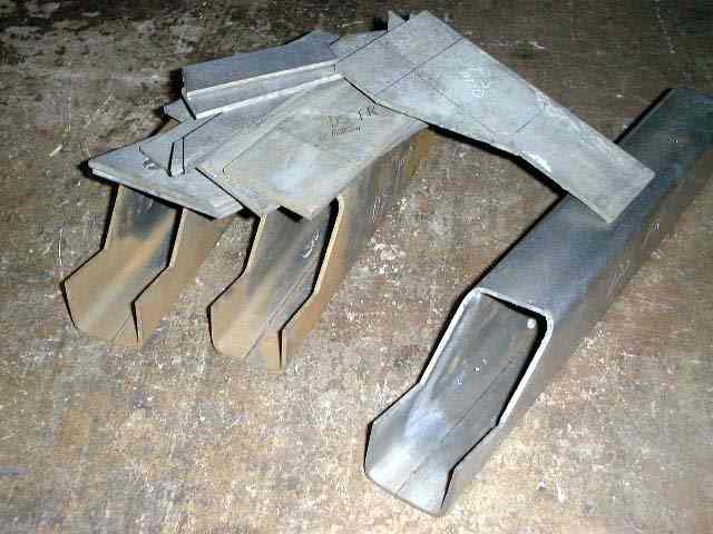
First we start with a bunch of plasma cut steel plate and outrigger material.
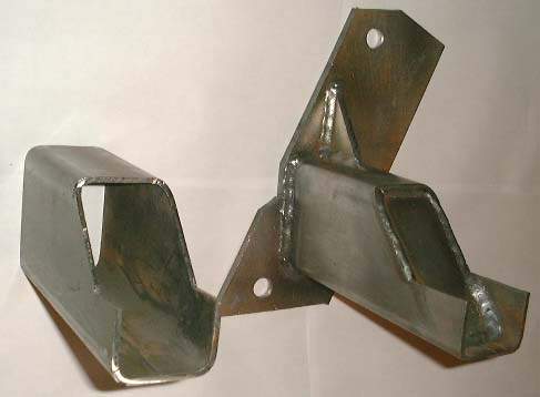
Next we see a picture of the rear US/PS outrigger. The US/DS is an exact copy except the plate is flipped front to back. The picture shows a cut section of 3"x2" material before being welded to the plate and internally boxed.
The next picture shows the US/PS rear outrigger welded to its siderail. The cap plate hasn't been welded in place yet, this is to allow the outrigger to be also internally welded to the siderail. All outriggers are attached to the siderail using this procedure except for the front US/PS outrigger (the one that goes under the catalytic converter).
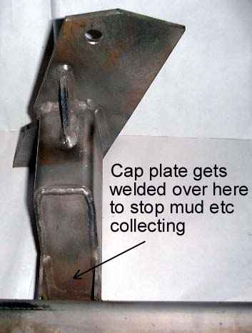
This next picture shows the US/DS finished and mounted siderail. You can see how the rear outrigger from the previous picture has been welded to the siderail. Once the outrigger is welded to the siderail (external and internal welds), a cap is welded over the top to prevent mud/water etc from collecting inside.
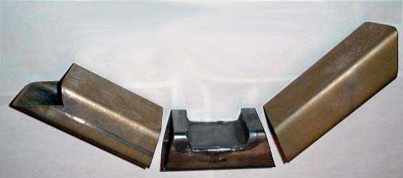
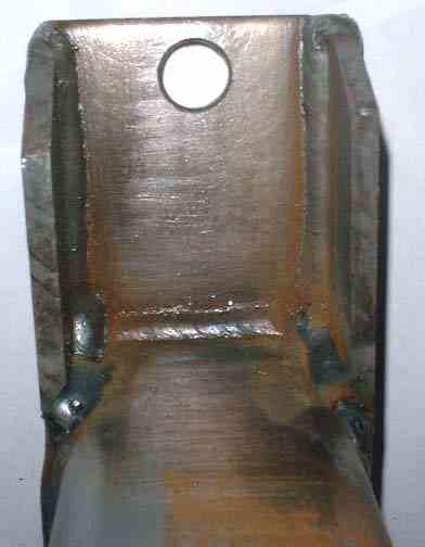
Next we see some of the fabrication details of the support that goes under the catalytic converter. I chose a design that would have minimal impact on the ground clearance of the support while attempting to provide a strong supportive mount.
The cutout in the middle of the outrigger is to allow clearance under the catalytic converter. On the later models, there are actually two sections to the converter and this outrigger goes under the flanges that bolt the two sections together. The piece that was cut from the middle section is flipped upside and then rotated 90 degrees and welded back in. Internal welds are also performed from each end to further strengthen this section.
The next picture shows the the fully welded support. The gussets on the chassis mounting plate have not yet been welded in place. You can see the four holes in the mounting plate that mate with the 4 captured nuts in the chassis (thanks toyota!).
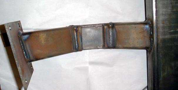
In addition to the 4 bolts on I've welded a tab on the bottom with a hole that picks up one of the larger cross member bolts. Since any likely force will be an upward push on the siderail, this front support would face a stress that would attempt to peel the bottom of the plate away from the chassis. The large crossmember bolt picked up by the bottom tab would resist that with a shearing force on the bolt.
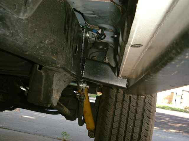
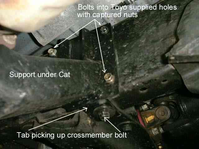
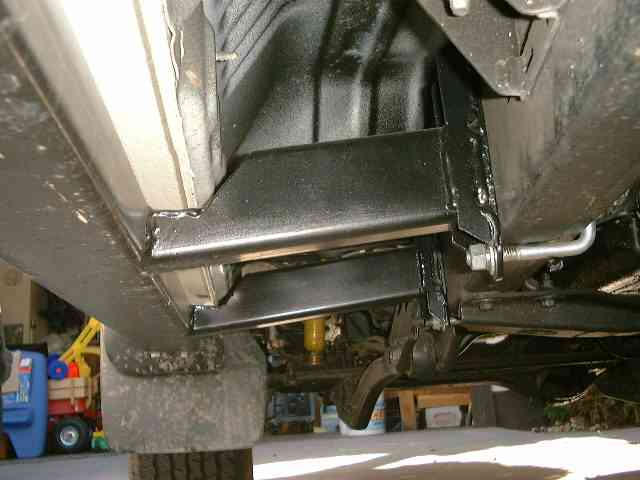
Here you can see the finished siderail bolted onto the US/PS side (looking towards the front of the vehicle from the rear). Visible is how the outrigger bolts to the chassis and clears the flange area between the two catalytic converter sections. As can be seen ground clearance is not compromised any further than by the cats themselves. In addition if I ever feel it necessary, the outrigger provides an ideal location to attach a skid plate for the cats.
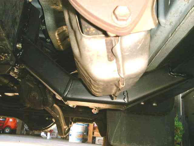
This picture shows the detail of how the catalytic outrigger is bolted to the chassis member. A 4th bolt is hidden behind the outrigger.
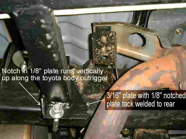
The following is a picture of the US/PS middle support. It's a tight fit between a body outrigger and an exhaust system bracket. I welded a 1/8" plate spacer to the 3/16" plate that the slider outrigger is welded to. The spacer has a notch to clear weld area on the toyota body outrigger.
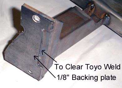
Next you can see a picture showing the 1/8" backing plate welded to the 3/16" plate. The notched section is clearly visible on the right of the plate. The final cap has not yet been welded in where the outrigger is welded to the siderail member.
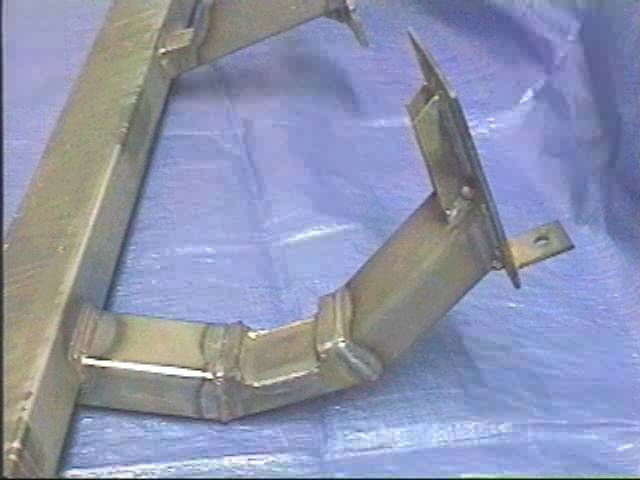
The following is a picture of the US/DS middle support. You can see the gussets that brace the outrigger to the plate that is U-bolted to the chassis. The outrigger member is welded (on all 4 sides) to the backing plate that is actually 3/8" wider than the 2" wide dimension of the outrigger. This leaves 3/16" each side for the gussets to be welded on each side. On the first few sliders, the gussets have a notch in them to clear the weld area from welding the vertical sides of the outriggers to the backing plate. Since then I only weld the top and bottom of the outrigger to the backing plate, then I weld on the gussets (without the notch) and then weld the gusset onto the outrigger. This saves a bunch of plasma cutting, welding, time and is just as strong.
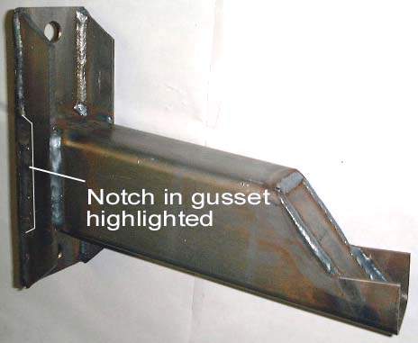
The following picture shows closer up detail of the US/DS front most outrigger. The outrigger is welded on the top and bottom edges to the back plate. Then the gussets are welded to the backplate (inside and out). Then I fully weld the gussets to the outrigger - this support isn't going to budge! Due to the chassis not being parallel to the body in both the vertical and horizontal planes at his point, I decided the easiest way to build this outrigger was to have it parallel with the chassis horizontal plane. This means that the end that is welded to the siderail is not parallel to it - seemed easier at the time and now that the templates are made I just build it the same each time.
This picture shows the US/DS front and middle outriggers and the U-bolts that retain them to the chassis. This side requires spacers to be placed between the brake line clips and the chassis to ensure sufficient space is available for the U-bolts to slip between the brake lines and the chassis. You wouldn't want to tighten up the U-bolts with the brake lines sandwiched between them and the chassis ;-)
![]()